|
Radar Speed Guns and Tuning Forks |
|
|
|
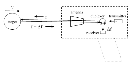
The transmitter of a typical radar gun is designed to emit a signal with a frequency of (say) 30 GHz. If it strikes a car approaching the gun at 50 mph, then by the Doppler effect the reflected signal has a frequency of 30 GHz plus 4480 Hz. The amount of increase is Δf = 2vf/c, where f is the transmission frequency, v is the speed of the car, and c is the speed of light. (This is just the first order effect, proportional to v/c. Strictly speaking there is also a relativistic correction, but that is proportional to v/c squared, which is negligible for measuring the speeds of ordinary objects, and far too small to be detected by an ordinary radar gun.) If the gun is intended to sense speeds between 10 mph and 120 mph it needs a receiving antenna that is sensitive to frequencies in the range 896 to 10752 Hz. The receiver is fed some of the transmitted signal along with the reflected signal, and those two signals combine to produce a “beat” with a frequency of 4480 Hz for a 50 mph car. |
|
|
|
|
|
|
|
Recall that a “beat” is produced any time two signals with different frequencies are superimposed. As they go in and out of phase, they alternately reinforce and cancel each other, which produces the “beat” at a frequency equal to the difference between the frequencies of the two signals. The receiving antenna of a radar gun is designed to be sensitive to this low frequency range, because the speed of the target object depends only on the small difference between the frequencies of the transmitted and received signals. The only disadvantage of sensing just the difference between the transmit and receive frequencies, rather than their absolute values, is that we can’t determine whether the object is approaching or receding, without adding additional features to determine whether the transmitted or the received frequency is higher. |
|
|
|
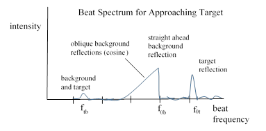
Of course, a radar gun doesn’t transmit a single linear beam, it emits a cone of microwaves, “illuminating” a fairly wide field of view, and the receiving antenna doesn’t just receive reflections off the intended target, it receives reflections off every object within the field of view. Consequently the received signal generally does not have just a single frequency, but rather a set of frequencies, corresponding to the relative speeds of every object in the forward cone. This is analogous to hearing a musical chord consisting of a set of different frequencies. For a compact object moving in front of a large background, a plot of the spectral analysis of the beat signal for a typical situation is as depicted below. |
|
|
|
|
|
|
|
The background would typically be the ground, trees, buildings, and so on, all of which share the same state of motion, although the cosine effect produces a ramp of background reflection frequencies coming from oblique returns. The top of this ramp is at the frequency corresponding to the speed of the radar gun relative to the road. The target might be an approaching automobile. From the received spectrum shown above, a simple radar gun would eliminate the noise and then select the maximum frequency with significant intensity, which is f0t in this example, and infer that this is the beat frequency of the reflection from the “target”, so the relative speed between the gun and the target would be computed as v = f0t c/(2f). However, since the background beat frequency is not zero, we can infer that the radar gun itself is moving relative to the background. A more sophisticated radar gun (typically used by police from a moving police car) can determine the speed of the target vehicle relative to the background (i.e., the road) by extracting the values of both f0b and f0t, from the reflected spectrum, and computing the speed v = (f0t – f0b)c/(2f). Thus, by subtracting the speed of the road relative to the gun from the speed of the target relative to the gun, we get the speed of the target relative to the road. |
|
|
|
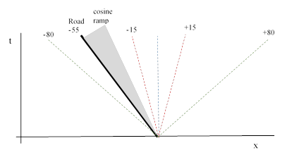
Of course, this computation entails an ambiguity, because the beat frequencies represent only the absolute values of the differences between the reflection and the emitted frequency, so we don’t know whether to add or subtract f0t and f0b. One method of resolving this difference is to detect the frequency of the beat signal that arises from the combination of the background and target returns. This is denoted as ftb in the plot above. As shown, we have ftb = |f0t – f0b|, signifying that the speed gun and target vehicle are both moving toward each other relative to the road (background). If, on the other hand, the speed gun were moving in the same direction as the target vehicle, the value of ftb would be |f0t + f0b|. However, this combination of reflected signals may produce a very low intensity beat, which may be difficult to detect. Another method is to distinguish the background by the ramp and amplitude. Then the only ambiguity is whether the target is approaching or receding. The figure below shows the worldlines of the background and target in the rest frame of the radar gun, illustrating the ambiguity. |
|
|
|
|
|
|
|
(In this plot we show only the sensed speeds corresponding to the beat produced by each individual reflection and the transmitted signal, not the speeds that could be sensed by examining the beat between the signals reflected off the target and road.) The device can recognize from the cosine ramp that the road is approaching the radar gun at 55 mph (which is to say, the radar gun is moving forward at 55 mph on the road), and we can consider two cases, in which we get a target return with magnitude (say) 15 mph or 80 mph relative to the radar gun. If we just examine the beat frequency, we don’t know the signs of the relative speeds. Hence in the “15 mph” case we can strictly infer only that the target is moving at either 40 mph or 70 mph on the road in the same direction as the radar gun. In the “80 mph” case we can infer that the target is moving on the road at either 25 mph toward the radar gun, or else 135 mph in the same direction as the radar gun. It’s worth noting that the cosine ramp prevents clear readings for speeds more than about 70% of the road speed. |
|
|
|
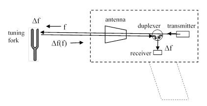
The frequency of the transmitter is constant, established by a solid-state oscillator with excellent stability, so the transmitter frequency almost never shifts. So, if the design frequency if f0, the actual transmitted frequency f can usually be assumed to equal f0 with high confidence. In fact, the typical radar speed gun computes the target speed using the formula v = Δf c/(2f0), without even bothering to measure f. However, it is obviously necessary to measure the received signal, and the receiver is designed to detect and measure a range of beat frequencies Δf, corresponding to the range of speeds that the radar gun is designed to detect. This “tuning” and analyzing of the received signal can potentially shift and become mis-calibrated, causing the radar gun to give erroneous readings. To test the gun, operators sometimes use small tuning forks, consisting of metal arms designed to oscillate at a specific frequency. When the tuning fork is struck (preferably on wood or some other solid less rigid than itself, to excite the ground mode and not more complex modes of oscillation) and placed directly ahead of the antenna of a radar gun, it causes the gun to give a specific speed reading (provided the gun is calibrated correctly). But how exactly does this work? |
|
|
|
In brief, when we place a metal object closely in front of the gun, and it vibrates at (say) 4480 Hz, this modulates the reflected signal (both amplitude modulation and frequency modulation) with a frequency of 4480 Hz, and the speed gun antenna picks this up and displays a speed of 50 mph. If the antenna tuning is wrong, it would display some other speed, so the operator would know the gun is not calibrated correctly. |
|
|
|
|
|
|
|
It’s important to note that the tuning fork is not sending a signal of 30 GHz + 4480 Hz, as would be the case for a genuine speed detection for 50 mph. The arm of the tuning fork is never moving at 50 mph (not even close). The tuning fork is only modulating the incident signal (which merely serves as a carrier wave), and this modulation has a frequency of 4480 Hz, which is equal to the beat frequency that would result from a Doppler-shifted signal reflected off an object approaching at 50 mph. In effect, the tuning fork is tricking the radar gun into thinking there is an object approaching at 50 mph, when in fact the tuning fork is just inducing a fluctuation in the antenna and receiver at the frequency of the beat that would be produced by an object approaching at 50 mph. |
|
|
|
Of course, if the transmitting frequency f is different from the design frequency f0, this test will not catch it, because it is just directly inducing a phony “beat frequency” into the receiver, and doesn’t involve the transmitter at all. An incorrect transmit frequency would result in incorrect speed readings (in the ratio f/f0), even though it passes the tuning fork test. The test only detects mis-calibration of the receiver and analyzer, not the transmitter. Fortunately, as noted above, the transmitter just has a single frequency oscillator that never changes, so it would rarely if ever become shifted, but the receiver and/or analyzer could more easily become shifted. This is why it’s worthwhile to have a simple test of the receiving calibration, even though it is really tricking the device and not performing an actual speed detection. |
|
|
|
The most thorough way to test a speed gun is obviously to actually perform a speed measurement on a real moving object with a known speed. This is done on a regular basis by operators of these devices who need to ensure that they are working properly. |
|
|
|
Incidentally, people sometimes mistakenly think that the tuning fork calibration works by putting the fork arms in motion at the calibration speed. It should be obvious that this is not correct, first because the arms of a tuning fork move at a range of speeds, positive and negative, on each cycle, second because the speed of motion differs along the length of the arms, and third because the maximum speed of the arms depends not just on the frequency but on the amplitude, which depends on how the tuning fork is struck. It would generate a specific maximum speed of arm movement only if struck with precisely the right force, and even then it would not remain constant, but would produce a continuously varying maximum speed, which would be different at different positions on the arm, and with different orientations. Also, to produce a maximum arm speed of 50 mph at the relevant frequency of (say) 4480 Hz would require the arm to swing a distance of 78 mm, whereas a typical tuning fork of this size has a maximum arm displacement of only about 0.02 mm, so the maximum speed of the arms of such a tuning fork is less than 0.1 mph, orders of magnitude less than the speed that corresponds to the induced simulated beat frequency. Fundamentally, the arms of a tuning fork simply do not move at a consistent reference speed – nor are they designed to do so. The characteristic of a tuning fork is not that the arms move at a specific speed (which they obviously do not), but that they oscillate at a specific frequency. Thus tuning forks do not (and could not) test radar guns by producing a moving surface at the calibration speed. Needless to say, they also do not work by means of acoustic sound waves, since the radar receiver isn’t affected by acoustic waves. It just so happens that the Doppler shift for electromagnetic radar frequencies at typical automobile speeds is in the range of audible frequencies for sound waves. |
|
|
|
Other examples of “spoofing” a simple radar gun can be given by anything that produces electromagnetic noise in the beat frequency range. For example, the electric motor of the fan in a car dash board produces electromagnetic noise in the 3000 Hz range, so it can produce a spurious reading if a radar gun is placed near the dash board with the fan running. Similarly by pointing a radar gun at a house fan or air filter we can get speed readings that match the frequency of the motors. It’s conceivable that the exposed blades of an open fan could produce an actual speed reading, but if the gun is pointed directly toward the face of the fan the blades are moving perpendicularly to the gun, so the cosine effect would eliminate nearly all of the relative speed. Pointing the gun in the plane of the fan disk could catch an actual speed signal off the tips, but the effective area may be too small to give a significant reading. The more common cause of a reading when pointed at a fan is due to the electromagnetic signal produced by the electric motor. This is confirmed by the readings produced by pointing the gun at, say, an enclosed air filter, with no visible blades. Also, there are online videos of tones of specific frequencies, and by playing these on a cell phone and pointing the gun at the phone, we get readings corresponding precisely to the speed with a beat frequency of that tone. This is because the electric coils driving the speaker in the phone generate a false beat that is picked up by the radar gun and registered as a speed. |
|
|
|
For a related discussion, see the note on LIDAR speed guns. |
|
|