|
Analytic Functions, The Magnus Effect, and Wings |
|
|
|
The essential features of aerodynamic lift can be explained in terms of two-dimensional potential flow, which satisfies the Laplace equation |
|
|
|
|
|
|
|
where ϕ(x,y) is the velocity potential. The streamline function, which is everywhere parallel to the flow velocity, also satisfies the Laplace equation. One technique for solving this equation for various boundary conditions is to make use of analytic functions in the complex plane. If we represent the point (x,y) in the two-dimensional plane by the single complex number z = x + iy, then the potential can be expressed as ϕ(z), i.e., a real-valued function of a complex variable. To begin, it's useful to recall some basic facts about complex functions. |
|
|
|
The general function of a complex variable is complex, i.e., it has a real and an imaginary part, so it can be written in the form f(z) = u(z) + iv(z) for two real-valued functions u(z) and v(z). Since the argument z = x + iy is complex, each of the functions u and v can be expressed as functions of the two real numbers x and y. Hence a general complex function f(z) of a complex variable z can be written as two real-valued functions u(x,y) and v(x,y) of two real variables. However, not every pair of real-valued functions of two real variables represents an analytic function of a single complex variable. |
|
|
|
Recall that for any given complex number z = x + iy there corresponds the complex conjugate z* = x - iy, and if we are given both z and z* we can obviously express the individual components of z simply as x = (z + z*)/2 and y = (z - z*)/2i. In contrast, if we are given only z as a single variable, there is no direct algebraic way of expressing the individual components of z. Thus if we require our u and v functions to be expressible purely in terms of z, without reference to z*, we exclude certain pairs of functions of the individual components of z. For example, we do not allow the pair u(x,y) = x, v(x,y) = 0, because this is tantamount to a function f(x+iy) = x, whereas there is no direct algebraic way of expressing x as a function of z (without also referring to z*). |
|
|
|
We can make the concept of an analytic function more rigorous by considering the conditions under which a complex function f(z) has a unique derivative with respect to z at a given point. When dealing with a real-valued function of a single real variable, the derivative of the function with respect to that variable is unambiguous, because there is only one way to vary a real number. In contrast, there are infinitely many ways of varying the complex variable z, because we can approach a given point in the complex plane from any direction. For the most general function of a complex variable we would need to consider the independent partial derivatives with respect to x and y. Analytic functions are a subset of all possible functions of a complex variable, because we they satisfy the requirement that the derivative of f(z) is unambiguous. In other words, we require that [f(z+δ) - f(z)] / δ has a unique limit as the magnitude of the complex number δ approaches zero, regardless of the direction of δ in the complex plane. |
|
|
|
To see what this implies for the individual functions u(x,y) and v(x,y), consider a complex increment δ approaching zero with an arbitrary orientation in the complex plane. Then δ can be expressed as a function of the variable magnitude h and a fixed angle θ as follows |
|
|
|
|
|
|
|
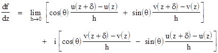
The derivative of f(z) is given by |
|
|
|
|
|
|
|
|
|
Carrying out the complex division, we have |
|
|
|
|
|
|
|
If the point of differentiation is z0 = x0 + iy0, the arguments of the functions u and v in this formula are |
|
|
|
|
|
|
|
so u and v are strictly functions of h. Hence the limit of [u(z+δ)-u(z)]/h in the above formula represents the derivative du/dh, and likewise the limit of [v(z+δ)-v(z)]/h represents dv/dh. We can express these total derivatives as |
|
|
|
|
|
|
|
|
|
|
|
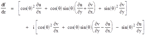
Substituting back into the expression for df/dz, we arrive at |
|
|
|
|
|
|
|
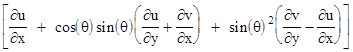
We require this to be independent of q, so that f has a unique derivative. The real part can be written in the form |
|
|
|
|
|
|
|
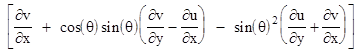
and the imaginary part can be written as |
|
|
|
|
|
|
|
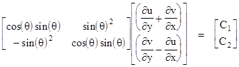
The individual partial derivatives at the point z0 are constants, so in order for both of the above expressions to be constant, independent of θ, there must be constants C1 and C2. such that |
|
|
|
|
|
|
|
The determinant of the coefficient matrix is just sin(θ)2, and we can solve this relation to give |
|
|
|
|
|
|
|
which is clearly impossible unless C1 = C2 = 0, which gives the Cauchy-Riemann conditions |
|
|
|
|
|
|
|
These comprise the necessary and sufficient conditions for f(z) to be analytic. |
|
|
|
Another way of expressing these conditions is found by considering the partial derivatives of an arbitrary (non-necessarily analytic) complex function f(z) = f(x + iy) with respect to x and y. Since f is a function of the real numbers x and y, and since x = (z+z*)/2 and y = (z-z*)/(2i), we can also express f as a function of the complex conjugates z and z*. Given this function f(z,z*), we can evaluate the partial derivatives |
|
|
|
|
|
|
|
|
|
|
|
Since f(z) = u(x,y)+iv(x,y), we can make the substitutions |
|
|
|
|
|
|
|
to give |
|
|
|
|
|
|
|
|
|
The second of these equations shows that the Cauchy-Riemann conditions are satisfied (and the function f(z) is analytic) if and only if |
|
|
|
|
|
|
|
This confirms our earlier assertion that f(z) is analytic if and only if it is directly expressible purely as a function of z, without explicitly involving z*. |
|
|
|
Returning to the Cauchy-Riemann conditions, notice that if we take the partial derivative of the left-hand equation with respect to x, and of the right-hand equation with respect to y, we have |
|
|
|
|
|
Partial differentiation is commutative (for continuous differentiable functions), so adding these two equations together gives |
|
|
|
|
|
|
|
Thus the real part of any analytic function is a solution of Laplace's equation. Likewise if we differentiate the left-hand Cauchy-Riemann with respect to y, the the right-hand with respect to x, and subtract one from the other, we arrive at |
|
|
|
|
|
|
|
so the imaginary part of any analytic function is also a solution of Laplace's equation. (Solutions of Laplace's equation are called harmonic functions.) |
|
|
|
These facts can be useful for analyzing two-dimensional potential flow for certain kinds of boundary conditions. If we can find a solution of Laplace's equation for a simple boundary in the z plane, we can apply any analytic mapping we choose, and map the boundary and streamlines to another complex plane. Since the streamlines conformed to the boundary in the original plane, they automatically conform to the transformed boundary in the transformed plane, and since the mapping is analytic, the transformed streamlines are solutions of the Laplace equation, just as were the streamlines in the original plane. Likewise the velocity potential maps from the original to the transformed plane. |
|
|
|
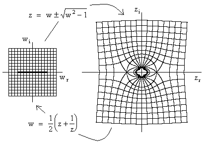
As an example, consider the mapping illustrated in the figure below. |
|
|
|
|
|
|
|
The analytic function |
|
|
|
|
|
collapses the unit circle in the z plane down to two straight lines on the real axis in the w plane. Now, it's trivial that the flow past a flat plane has purely horizontal streamlines and constant velocity, so the basic orthogonal grid lines in the w plane correspond to flow lines and lines of constant velocity potential. We can invert the function w(z) to give the analytic function |
|
|
|
|
|
|
|
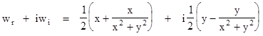
which maps from the w plane back to the z plane. Mapping the grid lines in the w plane gives the equi-potential and streamlines in the z plane for flow past a cylinder, as shown in the figure. Explicitly, the mapping from z to w gives |
|
|
|
|
|
|
|
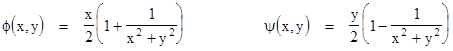
Since lines of constant wr are equipotential, and lines of constant wi are streamlines, the solution of Laplace's equation for normalized flow past a cylinder of unit radius is |
|
|
|
|
|
|
|
In terms of polar coordinates r,θ we have x = r cos(θ), so the potential can be written as |
|
|
|
|
|
|
|
It's easy to verify that this satisfies the two-dimensional Laplace equation in polar coordinates |
|
|
|
|
|
|
|
Of course, there exist other solutions for flow past a cylinder, perhaps the simplest of which is a free vortex, whose potential is of the form ϕ(r,θ) = -Cθ for some constant C. Hence the circumferential velocity of the flow at any radius r is C/r. The equipotential lines are simply radial lines, and the streamlines are circles around the origin. The constant C is proportional to the circulation Γ, which is defined as the line integral of the flow velocity component around a closed curve. From this it follows that C = Γ/2π. |
|
|
|
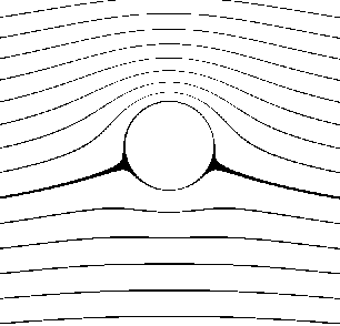
Since Laplace's equation is linear, the sum of two solutions is also a solution. Hence if we add an amount of circulation Γ to the original freestream flow, we have the total solution |
|
|
|
|
|
|
|
The corresponding streamlines are given by |
|
|
|
|
|
|
|
This gives a flow pattern such as the one shown in the figure below. |
|
|
|
|
|
|
|
The stagnation points have moved downward on the cylinder, because the clockwise vortex subtracts from the flow velocity on the bottom and adds to the velocity on the top. Differentiating the velocity potential with respect to θ, we find that the net tangential velocity is |
|
|
|
|
|
|
|
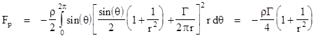
Now, according to Bernoulli's theorem, the pressure of the fluid with velocity v is p = (1/2)ρv2, where r is the fluid density (which we are taking as constant, i.e., we assume incompressible flow), and this pressure is applied normal to the surface, so the upward component is -sin(θ) p(θ). Integrating this pressure times the surface area for a unit length of a cylindrical surface of radius r (not necessarily the radius of the cylinder itself, which is r = 1), we arrive at the lift, i.e., the net upward force pressure force exerted on this cylindrical control volume |
|
|
|
|
|
|
|
Hence if we take r = 1 for the surface of the cylinder, and noting that there is no mass flow through the cylinder wall, and noting that the free-stream velocity at infinity is v0 = 1/2 flowing from left to right in our example, the net lift on the cylinder can be written simply as |
|
|
|
|
|
|
|
This is called the Magnus effect, named after the German physicist and chemist Heinrich Gustav Magnus (1802-1870), who made an experimental study of the aerodynamic forces on spinning spheres and cylinders in 1852, although the effect had already been mentioned by Isaac Newton in 1672 (apparently in regard to tennis balls), and investigated by Robins in 1742. This is the same effect that causes golf balls to slice or hook if they spun one way or the other. |
|
|
|
From examining the streamlines around the cylinder, it might seem surprising that any net lift is produced, because the air upstream of the cylinder is pulled upward along mirror images of the downward paths of air downstream of the cylinder. How can the air exert a net upward force if a net downward momentum is not imparted to the air? Well, in fact there is a net downward change in the momentum of the air, which we can see by considering a circular "control volume" of radius R surrounding the cylinder. Remember Newton's law states that F = dp/dt = d(mv)/dt, and since the velocity of the flow does not change as it passes through the boundary, we have F = v dm/dt. Hence we need to determine the mass flow rate through the boundary, and multiply this by the component of the flow velocity in the downward direction to give the upward force of reaction on the cntrol volume. The tangential component vθ of the flow velocity was given above, and the radial component is |
|
|
|
|
|
|
|
Consequently the mass flow (per unit length of the cylinder) out of an incremental angular slice dθ of the boundary of the control volume of radius R is |
|
|
|
|
|
|
|
The downward component of the flow velocity at this point is vrsin(θ) + vθcos(θ), so we can multiply this by the mass flow rate to give the rate of change of vertical momentum, and integrate this around the circumference of the control volume to give the net vertical force (per unit length) as follows |
|
|
|
|
|
|
|
where we have inserted the freestream velocity v0 = 1/2. To give the total overall net force on the control volume, we must also include the integrated pressure on the boundary, which we saw previously is given by |
|
|
|
|
|
|
|
Adding the momentum force and the pressure force, we arrive at the total force applied to the control volume by the interaction with the air |
|
|
|
|
|
|
|
which of course is precisely equal to the net lift L on the cylinder. At the surface of the cylinder the force is entirely due to pressure (because there is no mass flow across the boundary of the cylinder), but as we consider larger and larger control volumes surrounding the cylinder, the net force approaches an equal distribution, half due to the pressure, and half due to the momentum. Of course, this assumes the circulation of the flow extends indefinitely, whereas in fact the circulation flow breaks down at sufficient distances, and the organized pressure gradients are gradually dissipated through exchanges of momentum between neighboring parts of the fluid. At great enough distances the macroscopic momentum term disappears, and the total force is translated entirely into static pressure on the Earth's surface. In addition, it should be noted that the total vorticity - like angular momentum - is conserved, so there must be circulation opposite to the circulation around the cylinder. This typically arises as the flow around the cylinder is started, and it sheds vortices, which are then left behind in the flow, to eventually disolve. |
|
|
|
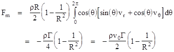
Incidentally, the Magnus effect sheds light on a a perennial question about the "correct" explanation for aerodynamic lift. Some old popular accounts of airplane wings refer to the contoured shape of a wing, and make statements suggesting that since the air must travel further on the curved side than on the flat side, but must take the same amount of time to go from the leading to the trailing edge, it must go faster over the upper (curved) surface, which by Bernoulli's theorem implies lower pressure, which produces lift. Unfortunately these popular "explanations" are not valid, because (for one thing) the air does not take the same amount of time over the upper and lower surfaces of an airfoil. In addition, these popular pseudo-explanations often don't mention circulation at all, which is crucial to the production of lift by an airfoil, just as it is for a spinning cylinder. In reaction to these pseudo-explanations, it is often pointed out that in order for lift to be exerted on an airfoil, it is necessary for some downward momentum to be imparted to the air. This is obviously true, but it sometimes leads people to overlook the existence of static pressure, and to completely reject the subtle aspects of aerodynamic lift, Bernoulli's theorem, and the effects of circulation. They imagine that a wing works essentially like a crude paddle deflecting airflow downward. Illustrations of the two common erroneous explanations of aerodynamic lift are shown below. |
|
|
|
Each of these obviously contains an element of truth, but neither gives an accurate impression of the actual processes involved in the production of lift by an airfoil. The preceding discussion of the Magnus effect shows that the actual explanation for aerodynamic lift, and the contributions of static pressure and momentum, are fairly complicated and subtle. (Of course, at the microscopic level the distinction between static pressure and dynamic force becomes blurred, because static pressure is actually exerted by dynamic exchanges of momentum between particles. For example, on the macroscopic level the force exerted by a contained gas on the walls of the container is purely static, and involves no changes or exchanges of momentum at all, whereas on the microscopic level the individual particles of the gas are continually changing their momentum as they bounce against the walls.) |
|
|
|
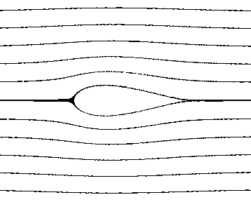
To see how complex analysis enables us to evaluate the theoretical lift of some non-trivial airfoil shapes, consider the flow pattern of the basic Magnus effect shown in the previous illustration. Recall that we deduced the basic flow past the cylinder by means of an analytic function that mapped a flat plate to a circle, and then we added circulation. Now suppose we tranform this final result back to the flat plate by applying the inverse transformation. This gives a flow field like the one illustrated below. |
|
|
|
|
|
|
|
|
|
We can see that the effect of the circulation around the plate is to move the stagnation points closer together on the bottom of the plate, much as it does on the circle. Now, a remarkable fact, first noticed by Joukowsky, is that the very same analytic function that transforms a unit circle (centered at the origin) into a flat plate also transforms circles of a different magnitude and centered away from the origin into shapes that are not perfectly flat, but that closely resemble practical airfoils. |
|
|
|
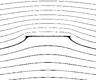
To illustrate, let us return to the basic circle without circulation, and suppose we enlarge the circle by a scale factor of 1.25 and shift the center to the left by 0.25. If we then map this back to the original "flat plate" plane, we get the symmetrical airfoil shape and flow pattern shown below. |
|
|
|
|
|
|
|
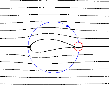
Just as with the cylinder, there is no lift on this object (nor is there any drag, in accord with d'Alembert's paradox). Now, returning again to our cylinder, let us not only magnify it by a factor of 1.25 and shift the center to the left by 0.25, let us also raise the center by 0.2. If we then transform this back to the "w plane", we get the asymmetrical airfoil and flow field illustrated below. |
|
|
|
|
|
|
|
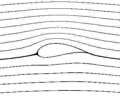
We have not introduced any circulation yet, but notice the abrupt turn that the flow is required to make as it exits the trailing edge of the airfoil. This is a theoretical solution of Laplace's equation for an ideal fluid, but for a real fluid this situation would generally result in a counter-clockwise vortex forming as indicated by the red circle. That vortex would then be "shed" into the downstream flow off to the right, but the total circulation is conserved, so a clock-wise circulation would form around the wing as indicated by the blue circle. This is called a bound vortex. As the forward speed of the airfoil increases, additional vortices would be shed, and the circulation around the wing becomes stronger. This process will continue, increasing the circulation arond the wing, until the flow off the sharp trailing edge of the airfoil is parallel to the trailing edge, as illustrated below. |
|
|
|
|
|
|
|
The circulation around the airfoil has the same effect as it does for the cylinder, producing lift. |
|
|
|
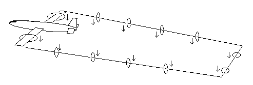
Throughout this discussion we've treated all these airfoils purely as two-dimensional objects, as if they were infinitely long, but of course real cylinders and wings have only finite length. Also, vortex lines cannot terminate in the flow, so for actual wings the vortex lines come off the wingtips and trail back into the flow. In fact, if it weren’t for dissipation into branching vortex lines, theoretically the lines would extend all the way back to the original vortex that was shed when the wing first began to move forward. The overall vortex line for an airplane wing theoretically would form a closed ring as shown below. |
|
|
|
The reality and strength of shed vortices is sometimes demonstrated when an airplane flies through the wake of another airplane. |
|
|
|
Incidentally, during the first world war when Albert Einstein was a professor in Berlin he wrote a paper in which he offered an explanation of aerodynamic lift. (This was in 1916, shortly after he completed the general theory of relativity.) He began “Where does the lift come from that allows airplanes and birds to fly?”, and went on to say he could not find even the most primitive answer in the published literature – which shows how little acquainted he was with the literature. In any case, Einstein decided the explanation for lift was the Bernoulli effect, and he sent a detailed proposal to a German aircraft company for a “humped wing, shaped like a cat’s back” which, he asserted, would provide maximum lift with minimum drag. As part of the effort to develop improved weapons for the German war effort, the company (Luftverkehrsgesellschaft, or LVG) actually constructed a prototype, which was flight tested by Paul Georg Erhardt, one of the pioneers of German aviation and head of the experimental department of LVG. Alas, the plane was a fiasco, barely able to get off the ground, and Erhardt considered himself lucky to have survived the test. Years later Einstein recalled the incident in a letter to Erhardt, saying “that is what can happen to a man who thinks a lot but reads little”. |
|
|